Sunday 5 November 2017

Surge Arrestor based on Quarter wave shorting stub

This technology is based on quarter wave transformation line.
The coaxial shorting stub applied for this purpose is short circuited at its end and its length is matched to the mid-band frequency of the operation band.It threby forms a band-pass filter.
Since lightning interference have a low frequency spectrum the shorting stub act as a short circuit, conducting the current to ground.

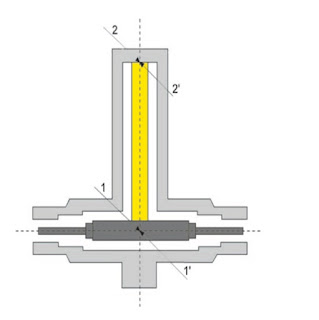
In regular operation, the RF signal reaches the entry of the shorting stub (shown here as point 1).
It then runs along the shorting stub up to the short (point 2). This corresponds to a 90° phase shift.
 At the short, the signal is reflected (point 2') –a sudden phase shift of 180° is created – and flows back to the start of the shorting stub (point 1'), where it arrives after another 90° phase shift.
As a result, the reflected signal is again in phase with the arriving signal. Therefore, the RF signal does not detect the short.
To go back to main page please click here


Surge Arrestor based on High Pass Filter


The concept behind this filter is that the low-frequency components of the lightning surge gets shunted to ground. As lightning energy has low frequency (lesser than 100KHz), these SA works as a high pass filter blocking surge energy.

To go back to main page please click here

Surge Arrestor based on GDT Principle


Depends on the working of Gas Discharge Tube.
A gas tube is an over voltage device that shunts current when a threshold voltage (the spark-over voltage) is reached. These are typically rated from 90V to 600V. It contains ionized gases.

When a voltage disturbance reaches the GDT sparkover value, the GDT practically shorts the line, diverting the surge current through the GDT to ground.

To go back to main page please click here

BASIC PRINCIPLE FOR RF SURGE ARRESTOR

There are basically three principles for coaxial SA devices.
Component based
1. Gas dischage tube (spark gap) Click here to know more about this principle
Filter based
2. High pass filter Click here to know more about this principle
3. Quarter wave shorting stub (Band pass filter) Click here to know more about this principle

Besides of these three, Designer uses Hybrid technolgy which combine two principles from above for its desired working.


RF Surge Arrestor

SA is a device to protect electrical equipment from over voltage transients caused by external (lightning) or internal (switching) events.

Concept behind Protection - Shunting
The goal of these devices is to protect the end product by shunting energy away. When the protection devices turn on, their impedance are reduced substantially. The circuit becomes current divider with most current going through the protection device.

Major Categories of RF Surge Protection Devices
1. Circuit Protection Components
Most common method of shunting transient energy is through circuit protection components such as Gas Tubes.

2. Filtering Components
Major method of shunting transient energy is through filter components such as inductors and capacitors.
Filter based RF SA's would have inductors and capacitors designed to handle kiloamp levels of surge.

To know on what principle these RF Surge Arrestor please click here.Basic Principle for RF Surge Arrestor

Sunday 23 July 2017

Interview Questions For Quality Engineer/Manager

Q1: Tell me something about yourself or your brief introduction.

Q2: Tell me about your present company.

Q3: What are your roles/ responsibilities in your present organisation.

Q4: What are your day to day's activities in your present organisation.

Q5: 7 QC tools

Q6: Who is responsible for handling customer complaints in your organisation? if you are responsible, how you handled the customer complaints?

Q7: What is 8D?

Q8: Different types of root cause analysis. give some example of using these method in your organisation.

Q9: What are your departmental goals?

Q10: Internal rejection rate or Internal DPPM, How you calculate & monitored?

Q11: Difference between correction & corrective actions.

Q12: What is/ are your achievement in your career?

Sunday 25 June 2017

Causes of Passive Intermodulation (PIM)

Ø Coaxial connectors - these connectors have joints between dissimilar metals and areas where oxidation can occur. Connectors that are assembled well using high quality components and water proofed well if they are to be used externally should last, but any connector will deteriorate with time. Connections made with poor connectors, or of the connectors have been assembled poorly will generate higher levels of PIM faster.
Ø Feeder lines - feeders such as coaxial feeders generate levels of passive intermodulation. The braid in the outer conductor provides many metallic interfaces in which passive intermodulation, PIM can be generated. Even if foil is used, there are interfaces between the layered construction of the foil wound round the dielectric. For applications where passive intermodulation is important coax with a good PIM performance can be bought. Some manufacturers may guarantee levels to below a given level, e.g. -140dBc, although at a cost.
Ø Joints where dissimilar metals meet and oxidation, etc. occurs converting the joint into an area that exhibits some diode effects.
Ø Dirty connections
Ø Loose connections and irregular contact areas, on a macroscopic or even a microscopic scale, can cause an inconsistent flow of current and generate inhomogeneous electromagnetic fields.
Ø General anodic effects
Ø The use of ferromagnetic metals, like iron, nickel and steel can give rise to passive intermodulation. These metals show magnetic hysteresis effects when energy is applied. This means that the resulting signal level is dependent, even to a small degree on input level. Hence this is a non-linear effect.
Ø Spark discharges can give rise to passive intermodulation. The spark will cause craters to be formed and some oxidation that will generate a diode effect. Sparks can result from poor connections or even the hot connection or disconnection of a connector.